Ball Sensors
Brief
To detect the IR ball in the lightweight division, we use a ring of 8 TSSP4038 IR Receivers. These give us a full 360-degree field of vision of the ball, with relatively good accuracy (minimum 45 degrees precision).
Development
We had previously tried the TSOP4038, in conjunction with a low-pass filter, but they didn't work out for us. The sensors would see the ball for a short period of time, after which they'd go blind. We assumed it might be to do with the low-pass filter we were initially using, to convert the digital signal to analogue, but upon further research, we realised it was to do with their AGC feature. Automatic Gain Control (AGC) is a mechanism in these sensors that tunes the gain control settings, to block out certain signals. It turns out this ends up blocking the ball's signal. This also explains why sometimes we'd turn off the ball, then on, and suddenly the sensor would begin working again.
We then switched to our current setup - the TSSP4038 - without the low-pass filter, but instead using software to measure the on-time of each sensor over a fixed sample period (ten wavelengths of the ball's IR emission). By sampling each sensor and measuring the 'on time' (the amount of time a low signal is read, which means the amount of time the ball is detected) we used these as weights for each sensor. We employed a weighted average (ball sensor direction angle multiplied by on time, then divided by total on-time) to give us an angle estimation of the ball relative to the robot. We can also use the sum of on-times to estimate the distance of the ball to the robot. This can be converted to an estimation in centimetres by plotting the distance of the ball on the y-axis, and corresponding on-time sum on the x-axis. A linear regression gives a simple conversion between the two.
Shielding
A crucial part of the ball sensors is the shielding. The algorithm assumes that each sensor has a limited field of view (around 45 - 90 degrees) and to achieve this we use a 3D printed shielding. The ring underwent several iterations due to the sensitivity of the sensors, as light leaks through any gaps it can find. Light also reflected a lot more than anticipated, even off any white walls in a room, or even the person testing the sensors. Our initial prototype, on perf-board, faced many problems as we initially assumed it was mainly from behind and around the sensors (in the plane of the perf-board) that caused the sensor to detect the ball. So we initially printed a minimal ring-like shield that encased the sensors all around, but not from the bottom (where the perf board was). We later realised the light was still bleeding through, so we designed a full enclosure around the perf board, with minimal exposure. This finally saw some results. However, during testing, we still found some sensors unintentionally being triggered. This was due to our testing environment, and not the sensors themselves. It turns out that the white walls in the room, as well as the person testing, were enough of a surface to cause the light to reflect and trigger a sensor even 180 degrees from where the ball was.
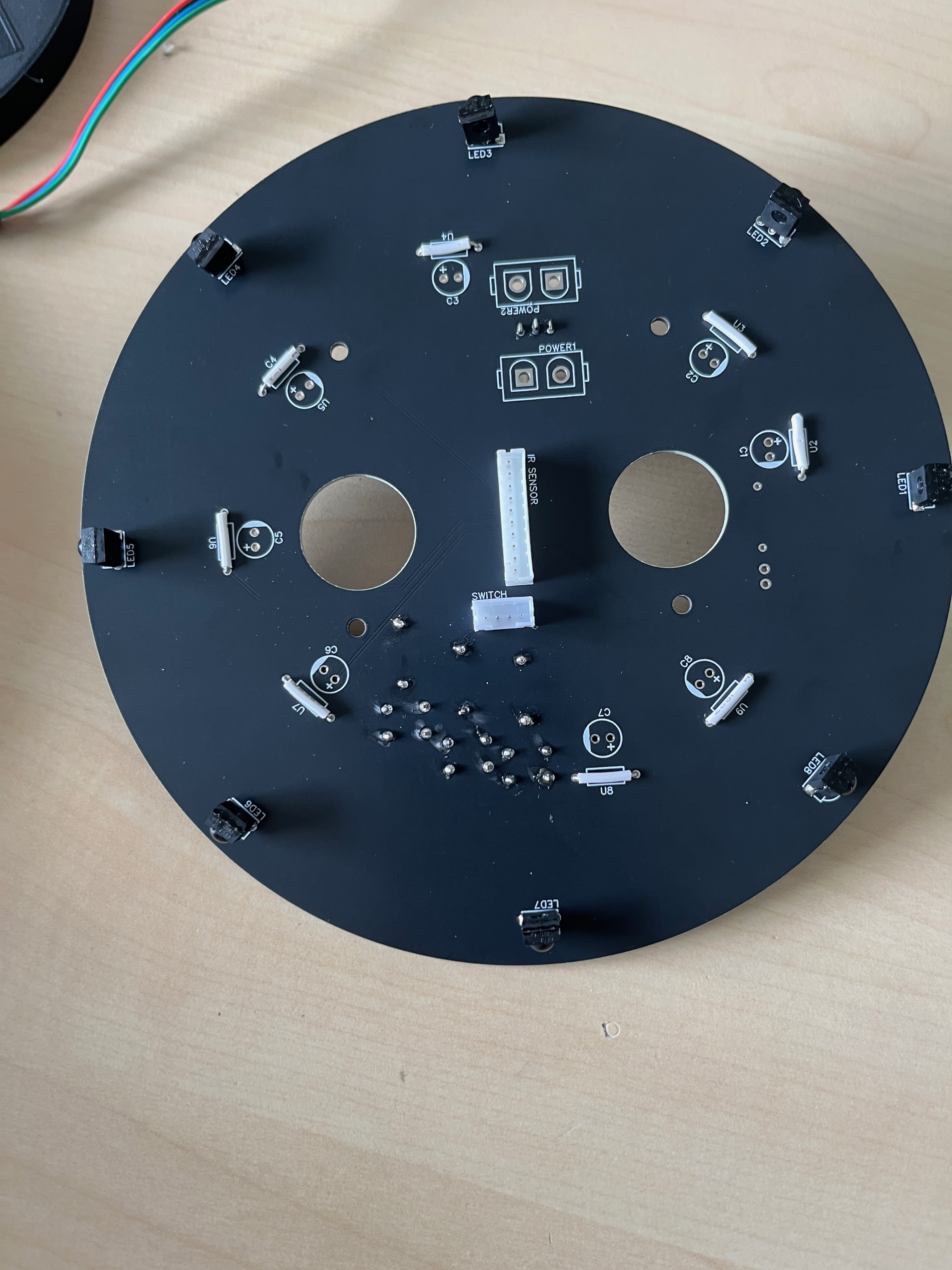
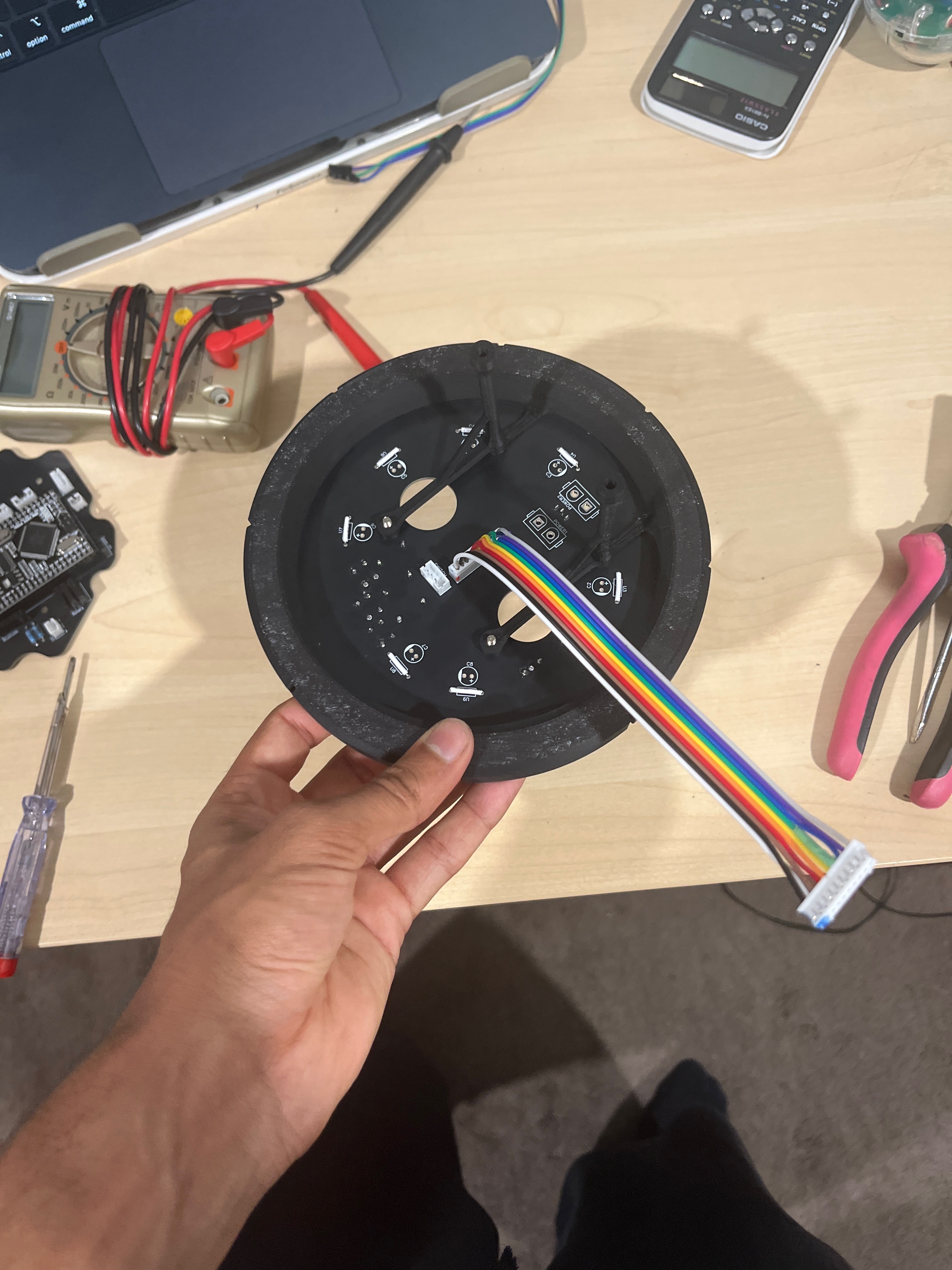
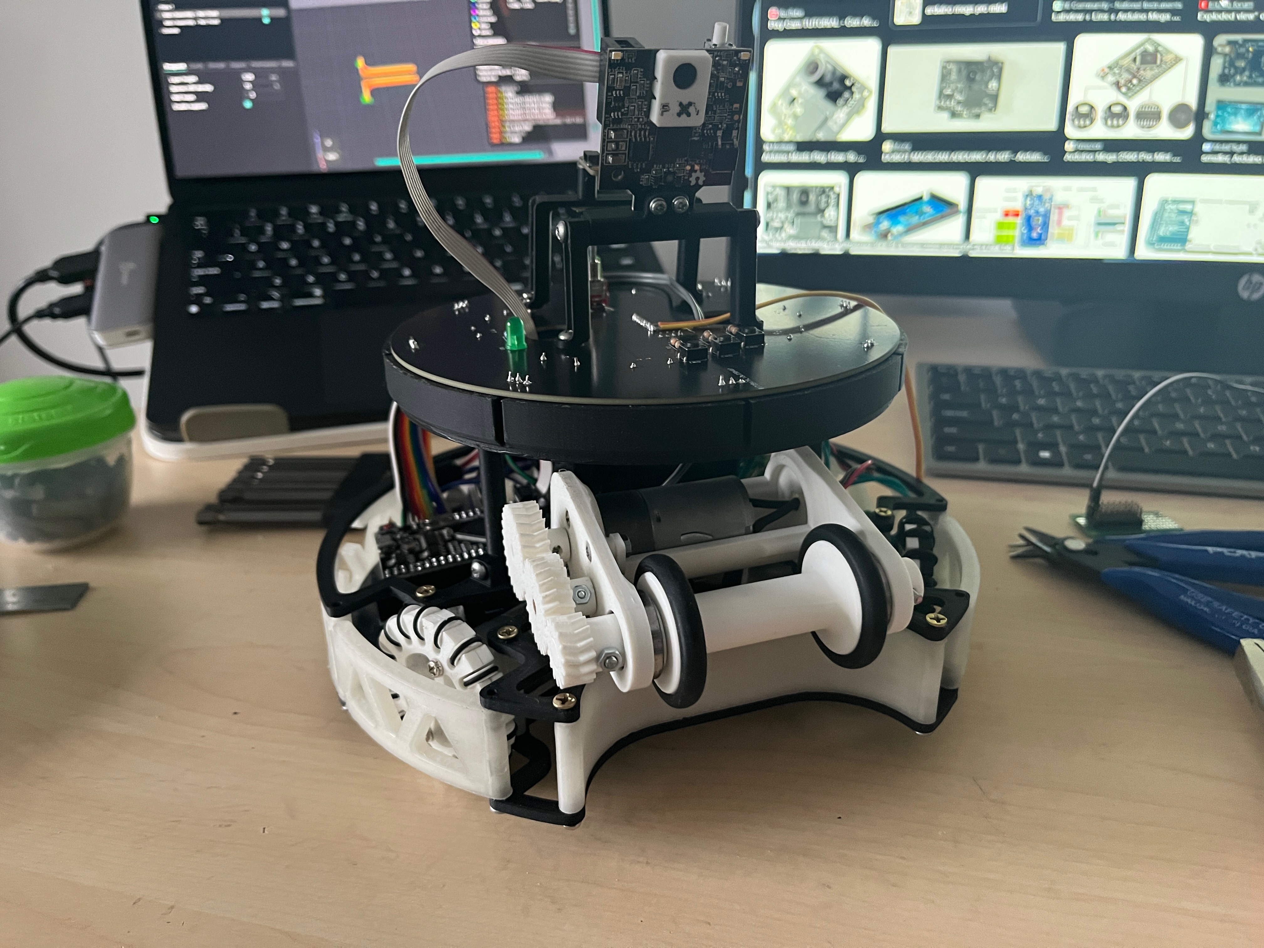
We then graduated to a full-fledged custom PCB. The shielding for this is a ring that fits on top of the ball sensor PCB and fully encases each sensor aside from a frontal slit. The slit is around 2mm in width and 10mm in height. This prevents any light from behind, on top, or outside the intended field of view of each sensor. The black PCB prevents light from coming from under the sensor. We also experimented by coating this shielding in black paint, which helped reduce some of the light bleed. Furthermore, we used 50% infill density when printing the parts to protect the sensors further. This shield gives us adequately accurate and precise ball detection.
Some photos of how they turned out: